
PA3CLQ's Leuke Linken Nr. 471
Beste mede amateur,
Dear fellow amateur,
In deze mail staat een link waarop het vijfendertigste
DKARS-Magazine is te downloaden.
This mail contains a link which
the 35th- DKARS-Magazine is available for download.
De Dutch Kingdom Amateur Radio Society is een stichting die de
belangen wenst te behartigen van ALLE radioamateurs binnen het gehele
Koninkrijk der Nederlanden.
The Kingdom Dutch Amateur Radio Society is an organization that seeks to represent the interests of ALL radio amateurs throughout the Kingdom of the Netherlands.
De DKARS doet niet aan copyright en het staat
een ieder vrij om deze link aan zoveel mogelijk radiovrienden door te
sturen.
The DKARS does not copyrighted and any
person shall be free to forward this link to as
many radio friends.
DKARS Magazine verschijnt 1x per maand en wij
stellen het uiteraard op prijs als je ook (radio amateur gerelateerde)
bijdrages wilt leveren.
DKARS Magazine appears 1x per
month and we obviously appreciate it if you (related radio amateur) to provide contributions.
Namens de Dutch Kingdom Amateur Radio Society wens ik je veel leesplezier nadat
je op deze link hebt geklikt:
On behalf of the Dutch Kingdom Amateur Radio Society, I wish you pleasant reading after you click on this link:
http://downloads.dkars.nl/DKARS%20Magazine%20201709.pdf
Wil je in plaats van een PDF te downloaden
het Magazine on-line doorbladeren?
Dat kan ook, ga dan naar deze link:
Want to download the magazine browsing on-line instead of a PDF? This can also go to this link:
https://issuu.com/pj4nx/docs/dkars_magazine_201709
Mist u een DKARS-Magazine kijk op:
Do you miss a DKARS-magazine see:
http://www.dkars.nl/index.php?page=magazine
En tot slot: heb je kopij, een mening, gevraagd of ongevraagd advies: dat kan 24 uur per dag, 7 dagen per week via
And finally, do you copy, an opinion, solicited or unsolicited advice: it 24 hours a day, 7 days a week through
73 namens de DKARS
Peter de Graaf
PJ4NX en PA3CNX
Secretaris DKARS
Key
Thought I would leave this here for those who like cooties.
Jeffry Gray
New 630M and 2200M Bands
OFFICIAL: 630 and 2200 Meters Open Oct. 16th.
Note, one must register and wait the 30 days.
https://swling.com/blog/2017/09/fcc-opens-630220-meters-october-16-pre-registration-required/
73 Mark K3MSB
I registered on Friday.......
but haven't gotten a response yet. I have a rig that can receive & transmit on 630m but I need to get an amp.
Can only output 100 mW at the moment and I'm
not into QRPppp, haha...
73, Drew AF2Z
One easy trick to help keep a light weight Cootie from moving around is Double Sided tape.
Cheers, Mike Pilgrim, K5MP
88 ft feed with 450 ohm ladder-line
Advice: going up with 88 feet wire with 450 ohm ladder-line - what length of ladder-line to use in order to have maximum multi band coverage to L-tuner?
Need actual experience not theory.
Antenna about 40 ft height between trees with
radials under it.
Dave Little - AF5U
I am afraid you have too many variables here to get an exact answer based on experience.
I have put up many open wire fed antennas over the years - most recently a 160 meter horizontal loop at 45' and it took a lot of experimenting with exact antenna length vs feed line length to come up with a "best compromise" feed line length. Mine is 52.5' and slightly shorter would have been better, but that brings us to the "proper feedline length is the one that reaches from the antenna to the tuner" as I could go no shorter than 52.5'.
I have usually had to cut, prune, add, etc to come up with a good length on any OWL fed antenna.
I usually keep some junk line laying around and just temporally cut and splice, etc until I get close, then install some good line of a somewhat longer length and start trimming.
There are charts available of lengths to
avoid (1/4 wave) etc. but when doing multiband that involves compromise.
73, Dave - W3NP
Dave,
Try QRZ.com Technical topics Forum, Antennas
etc
CW is Real Radio 73, John...K8JD
SKCC Group
Dave,
Look up a W3EDP antenna.
Super luck here with this antenna.
KF5AZ
Dave,
It has to do with optimum lengths depending upon your preferred
frequencies of operation.
Check out :
http://www.w5dxp.com/goodbad/goodbad.htm
http://w5dxp.com/notuner/notuner.HTM
Those pages helped me to design my own 135'
doublet which is up 55' over very poor ground.
73, Ed - ad7gr
Dave,
Based on experience, you will be very hard to beat the ZS6BKW 5
band no tuner needed doublet.
I've been using them for years.
Very efficient, less than 94 feet of wire and less than 41 feet of 450 Ohm window line.
It will give you 5 bands with no tuner and
with minimum (most internal tuners) it will work very well 80 through 10
meters.
If you have any problems finding info or need explicit instructions just drop
me an email off list and I'll forward the files to you.
73 for now, Randy_KB4QQJ
Dave,
Actually your question should be rephrased
"what lengths of feed-line should I avoid if I want to operate
multi-band" with this antenna?
If you can tell me how long you need the feed-line to be, I can tell you what
the "problem" lengths are that are close to that so that you can
avoid them.
One of the Antenna books that I have has a table that correlates the "half the flat-top plus the feed line length" and shows lengths that won't work for all of the HF bands.
It is a matter of figuring out how much feed
line you need to reach the tuner and then figuring out if that length + 44 ft
corresponds to a problem length on one of the bands and then adjusting
accordingly.
I many need a couple of days to figure out which book this info is in, but I
will gladly help you out.
Cheers,Michael VE3WMB / VA2NB
See
http://www.qsl.net/w5rin/Projects/Antennas/ae5vv/W3EDPAntenna.pdf
http://www.nc4fb.org/wordpress/w3edp-multi-band-antenna/
Editor
Hi Everyone,
Once again, the Alton Chapter of the Morse Telegraph Club will be demonstrating Morse at the Prairieland Heritage Museum Fall Festival and Steam Show. Here is a link to their website:
https://prairielandheritage.com/
Paul Roady, former GM&O Operator and I will have a setup and, if all goes as expected, connected to Morse KOB Wire 11.
Though the show is Friday, Saturday, and Sunday, I will be there only on Friday and Saturday.
Once I confirm my connection, I will send a follow up e-mail to the list.
Please drop by the wire and say "hi" if you can.
Even better, if you can come to Jacksonville, we'd love to visit with you!
73, Derek Cohn
Amateur Radio Station - WBØTUA
Morse Telegraph Club - Office UD, Sine DJ
Its about the Original American Morse Code
see PLL 469
Editor
I have uploaded to the files section the 65 page synopsis of this famous case, heard by the US Supreme Court in 1856.
The PDF is 65 pages long, but you can breeze through it rather quickly.
73 SW & (abram burnett)
Quote
U.S. Supreme Court
O'Reilly v. Morse, 56 U.S. 15 How. 62 62 (1853)
O'Reilly v. Morse
56 U.S. (15 How.) 62
Appeal from the circuit court of the UNITED STATES FOR THE DISTRICT OF KENTUCY
Syllabus
Morse was the first and original inventor of the electro-magnetic telegraph, for wich a patent was issued to him in 1840.
His invention was prior to that of Steinhiel of Munich or Weatstone or Davy of England.
Their respective dates compared.
Unquote
See attachment pse
Editor
Line Wire from Donner
A friend just gave me a Brookfield Bee-Hive spiral-groove glass insulator from the Southern Pacific at Donner Pass, California.
The spiral-groove insulator was invented by Dr. John Barclay, a dentist and a telegrapher, who eventually became the Chief Engineer of Postal Telegraph. Barclay was the man responsible for the "Barclay snare-drum relay," the little gouges on the bottom of binding posts to keep them from rotating on the wood surface, and other inventions.
His spiral-groove insulator was a 1907 patent, and its stated purpose was to afford a quick-change insulator where the lineman did not have to remove and replace the tie wire when doing an insulator change-out.
This insulator still has a chunk of steel line wire tied to it.
I put a caliper on the line wire and it measures 0.232" dia.
The Electrician's Handbook tells me that #4 wire is (was) 0.234" dia, so I conclude that this wire was #4, was originally 0.234". and that 0.002" of its original dimension has been lost through corrosion.
The wire is bare, i.e. is has no insulation.
The line wire itself appears to be bare steel, not Copperweld, and that is strange because Copperweld was available in the 1890s.
Filing the surface of the line wire with a small file does not reveal anything other than steel on the surface.
But the tie wire is #8 and the greenish oxidation on it indicates that it may have been Copperweld.
I have interviewed a number of old railroad linemen here in Pennsylvania, and the biggest wire they have told me about was #6 on railroad pole line.
So I am curious what #4 wire might have been used for. Since the wire is un-insulated, I don't think it would have been used for 440 AC... would it?
Probably only Wire Chief Trump can guess at this one...
73 SW & (abram burnett) SlowSpeedWireGroup
Only thing I can guess about using No 4 iron (steel) wire would be to ensure it wouldn't be broken down by ice/snow/ wind loading.
The Western Union typically used No. 6 BWG ( 0.192 in. Dia) galvanized wire on single wire lines in heavy weather districts, and two No. 6 wires on the top arm in the pole pin positions if the line had two or more wires on it, for the same reasons.
These big heavy wires seldom broke, but the poles and crossarms suffered instead.
As to the tie wire….
copperweld wire for the tie wires would not have been used due to It's stiffness and this being difficult to work with.
We used No. 6 iron and No 8 iron tie wires on those sizes of wire. (same wire as the line wire being tied to the insulator).
Line wire in the insulator groove, tie wire around the insulator in the groove, with one turn around the line wire on each side of the insulator.
Ends of the tie wire pointed “down” to let water drip off.
Hard drawn Copper and copperweld line wire tie wires used same size wire, but of soft annealed copper, and cut longer than iron tie wires.
Easy to work with and it was applied differently on the insulators.
Line wire in the groove, tie wire around insulator in the groove, crossed over on top of the line wire and then several”long”wraps (not “buttons”) around the line wire on each side of the insulator.
Ed. FB
http://www.insulators.info/articles/cd_147_the_groovy_insulator-1.pdf
http://www.insulators.info/articles/cd147.htm

http://www.hemingray.info/database/detail.php?cd=147
https://www.ebay.ca/dsc/Bottles-Insulators/29797/i.html?Brand=Milton%2520Bradley&_nkw=groove
Editor
The Morsum Magnificat Signal
I worked with Rinus Hellemons PA0BFN and Dick Kraayveld PA3ALM (now PA8DWN) in producing the last issues of Dutch MM (DMM) and the first issues of English MM (EMM). When Rinus died DMM ceased publication and I continued publishing EEM single-handed, from1986 until 1990, when Geoff Arnold G3GSR (now SK) joined me to continue producing the magazine. Zyg Nilski G3OKD took over as editor in EMM62, February 1999, with continuing assistance from me and the last issue was EMM89, March 2004.
Regarding the MM call signal, the following appeared in EMM40, June 1995:
“3.553MHz is the Morsum Magnificat “chat” frequency where MM readers, particularly those from Holland and nearby countries, identify each other by sending the MM signal which appears on the front cover of every issue of the magazine.
We frequently receive enquiries from new readers as to just what that signal is. It was the on-air “signature” of the magazine’s founder, Rinus Hellemons PA0BFN, and is actually two letter V’s, the second sent more slowly and hesitantly than the first. Ed.”
It was slightly more complicated than that. The apparent VE or SN is the letter V with the first dit of the second V added to it. The second V is represented by the extra dit on the first V and the separate “dit’, “dit”, “dah” all sent slowly and separately in the second part of the signal with the last dah extended; i.e. didididahdit dit dit daaaah. The last dah cannot be extended when using an elbug of course, only with a straight key.
Rinus told me that it originated from the time when he was in the Air Force and had time to spare when there was no signal traffic. As he idly played with his key he practised different combinations of letters, breaking them up to create interesting patterns. He liked the sound of the simple combination of two V’s broken up and he began to use it on the amateur bands as his own identification signal.
When he founded MM it was a natural progression for his special VV’s to be adopted as the MM call signal.
In EMM 41, page 43, Monika Pouw-Arnold, PA3FBF, wrote “Perhaps stations out of range from European transmissions on 3.553 could look for each other (using the MM signal!- Ed) on frequencies ending ‘53’; e.g., 14.053, 21.053, 28.053, 28.153. This idea was originally suggested by Rinus Hellemons, PA0BFN, in the early days of MM.”
I, too, used the call on 3.553. I kept in touch with Rinus on frequency to discuss MM matters and worked many MM readers as well. It is never heard today, of course, except that I sometimes use it as part of my CQ calls on 3.553 and 14.053 as a nostalgic tribute to Rinus, and in the vain hope that an old reader of MM might recognise it and return my call! It never happens of course but wouldn’t it be wonderful if the renewed interest in MM created some sort of revival!
This interest has been created by the release of all 89 issues of the English language version of MM for free download from http://www.n7cfo.com/tgph/Dwnlds/mm/mm.htm together with other MM publications, the Q & Z Codebook, The Story of the Key, The Key WT 8A Survey, and a Comprehensive MM Index covering all 89 issues..
The website, hosted by MM enthusiast Lynn Burlingame N7CFO, has attracted nearly 15,000 “hits” in five months, demonstrating that there is still much interest in Morse telegraphy.
Regarding the logo “Flying the Flag for Morse” the motto was my idea and the logo was designed by Geoff Arnold G3GSR. It first appeared on the cover of EMM27, April 1993.
Tony Smith G4FAI.
[SSN] Tamitha Skov, Solar Space Weather report
The latest report on Space Weather from Tamitha Skov.
I always enjoy these bulletins.
https://www.youtube.com/watch?v=gIhABAXtV4Y&feature=em-uploademail
Cheers, Darrel.
September 14: Thursday's sessions.
QRN on both bands, but better copy on
everyone on 30m.
Today was a good day for me.
I've been suffering from power line QRN for the last 6 months.
This had been giving me an S7 - S8 noise level on 20m and 17m, although the rx noise blanker can cut it down a lot.
Unfortunately my rhombic is beaming right at the source of noise.
After many complaints from me, this afternoon the power company came and fixed the problem within 5 minutes.
It was some arcing to the ground wire at the top of a 14 kV power pole, about a quarter-mile from me.
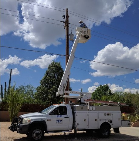
73 all, Darrel, aa7fv.
This was put on the fists reflector and I thought it would be good for us as well,
73 Rich G4FAD..
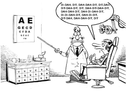
Excellent no ?
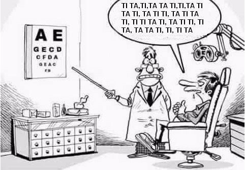
I’ll do that during my future medical visit…
F5NFB Joël
73, David Ring
73 es 77 de Lou VK5EEE
Pic of my damaged right dumb.
A "crack" due fall of stairs
(far from home: Lourdes ) also two ribs damaged…. seems the candles and holy
water did not help at all there in Lourdes, pity me.
Sri no pics of nurses.
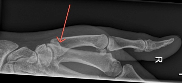 Cheerio, Jos ON6WJ
Google Groups "SSN-ML" group.
SideSwiperNet Group
By OM Yann F5LAW
73, from the town at the rivers "De Bergsche Maas" and "De Dongen" Geertruidenberg (800+ years city rights) at: 51.702211N 4.853854E
Editor Jan Pieter Oelp PA3CLQ
-30-
My simple website about Gigantic DF-Antennas
Part 1 "DF-Antenna Wullenweber Array"
Part 2 "DF-Antenna USSR Variants"
Part 3 "DF-Antenna USA Variant"
Next Part 4 "USSR OTHRA DUGA 1,2 & 3" at: