
PA3CLQ's Leuke Linken Nr. 439
Dag
Jan (clq),
Misschien oude koek, maar ik wil graag melden dat ik met foto vermeld staat in
het blad Immaterieel Erfgoed, nr. 1 (2015), (A)
een uitgave van het Nederlands Centrum voor Volkscultuur en
Immaterieel Erfgoed (B)
https://www.veron.nl/wp-content/uploads/2015/02/IE_0115_morse.pdf (A)
http://immaterieelerfgoed.nl/ (B)
http://immaterieelerfgoed.nl/vakblad-immaterieel-erfgoed_62.html
73's Jan PA3EGH
Zie bijlage

Here's
a link to the NASA std. version of the WU/lineman's splice.
http://makezine.com/2012/02/28/how-to-splice-wire-to-nasa-standards/
Telegraphy is still relevant!
73, Chip
 REM :
REM :
Saw that.
Didn't impress me because I already knew it by telegraph splice.
So, brushed it off as OLD old old old news.
Ted Wagner
REM :
All old hat, have already learned ~1951
Editor
Beste mede amateur,
Dear fellow amateur,
In deze mail staat een link waarop het vijfentwintigste en
zesentwintigste DKARS-Magazine is te downloaden.
This mail contains a link which the 25th- DKARS-Magazine is
available for download.
De Dutch Kingdom Amateur Radio Society is een stichting die de
belangen wenst te behartigen van ALLE radioamateurs binnen het gehele
Koninkrijk der Nederlanden.
The Kingdom Dutch Amateur Radio Society is an organization that
seeks to represent the interests of ALL radio amateurs throughout the Kingdom
of the Netherlands.
Namens de Dutch Kingdom Amateur Radio Society wens ik je veel
leesplezier nadat je op deze link hebt geklikt:
On behalf of the Dutch Kingdom Amateur Radio Society, I wish you pleasant reading after you click on this link:
http://downloads.dkars.nl/DKARS%20Magazine%20201607.pdf aug 2016
http://downloads.dkars.nl/DKARS%20Magazine%20201608.pdf aug 2016
Wil je in plaats van een PDF te downloaden het Magazine on-line
doorbladeren?
Dat kan ook, ga dan naar deze link:
Want to download the magazine browsing on-line instead of a PDF? This can also go to this link:
http://issuu.com/pj4nx/stacks/908f8b31fac742848591b9f65d971397
https://issuu.com/pj4nx/docs/dkars_magazine_201607 aug 2016
73 namens de DKARS
Peter de Graaf
PJ4NX en PA3CNX
Secretaris DKARS
Band Checking looking for propagation.
Band Check, to see if there is propagation at all try the WWV/WWVH and CHU time signals.
WWV and WWVH are on 2.5, 5. 10, 15, 20 and recently reactivated 25 MHz from near Boulder, CO and Kekaha on Kauai Island, HI.
CHU is near Ottawa, ON on 3.330, 7.850, and 14.670 MHz.
They are active 24/7 and you can see if there is any propagation at least to those 3 transmitter locations from your QTH.
CW is Real Radio
73, John Davidson K8JD
Ground returns
How deep must a ground rod be driven at any given location to create an acceptable ground return?
I have driven 8 foot ground rods for ground protection, but was curious if the same length of rod is needed to achieve an effective ground return.
How was a proper ground return determined when setting up a telegraph line?
73, Joe
REM :
Answer to your question….it depends…
For telegraph earth return purposes:
Generally a “good” earth ground can be obtained by driving copper-clad steel rods into undisturbed earth down to a depth where the earth is moist and not frozen.
If multiple rods are driven, sometimes two or three rods connected in parallel and spaced several yards apart will improve the connection, however more than three rods reaches the point where further improvement is not obtained.
A hole can be dug down several feet to moist earth and a metal plate of a few square feet area can be buried there.
Other “good” earth connections can be made by placing metal screens or plates on the bottom of a river, creek, pond or other body of either fresh or salt water.
Extremely dry sandy earth or frozen earth will not be a good place to place ground electrodes of any kind.
It may be impossible to get a circuit at all.
The connection must reach moist or unfrozen earth.
A “proper” ground has been obtained when you can pass full line current through the instruments and wire comprising the circuit from the battery supply voltage applied.
Be aware that it will take upwards of 40 volts or so of Battery in the circuit to get adequate line current (40 to 50 Milliamperes) particularly on “short” ground return circuits of a few hundred yards to a few miles in length.
After that, for longer circuits the resistance to circuit tends towards zero Ohms.
On longer lines , an earth-return circuit will have half the resistance of a metallic loop of the same length.
That is, the contribution of the earth path to the resistance of the circuit is nil.
Ed FB
REM :
Ed and Kevin
Thanks for lesson in earth return grounding.
I had no idea that are so many variables to this topic.
I guess person assumes the conditions are the same if they have never applied the practice outside your home territory.
I have wanted to set up a circuit to play around with just grins, but space limitations does not make this a possible.
Thanks again, Joe Fehrenbacher N0PME
MTC Office Call: MV
REM :
Hi Joe,
When you say you don't have space, I put together a simple "Civil War" ground return circuit entirely in my back yard.
My wire was only about 100 feet long.
It worked quite well.
I used my house copper water service for the ground at one end of the wire in my kitchen.
This was a real good ground as it interconnected the copper water service feed line, the underground electrical supply ground and the "black iron" gas feed service (this I think just through the commonality of the water and gas service at the gas water heater). I checked the connections between all three with an ohmmeter.
The ground at the "field office" end was just a replica Civil War bayonet pushed into damp earth as shown in that drawing "A Field Expedient" from J. Emmet O'Brien's book about his experiences as a Civil War telegrapher.
This was documented in a two page article in the Summer 2011 issue of "Dots & Dashes" (pages 8 & 9).
The ground resistance was the major source of the overall resistance as the ground run was short, but the earth was damp and I was able to get almost 40 ma through the two station circuit with just 30 VDC "main battery" (a single Radio Shack wall wart).
73, Chris Hausler
REM :
Thanks Chris, I will have to play with this fall when it's cooler.
Now I have another question.
Did the first-time Atlantic underwater cable use earth return as part of the circuit? If not, how did this circuit work?
73 Joe N0PME
REM :
Hello Joe,
In response to your question regarding Atlantic cable operation:
Undersea cables did not use the standard landline Morse system we are familiar with. Instead, the central internal conductor of the cable was used in conjunction with the outer metallic body of the cable (and subsequently the sea) as the other conductor.
Messages were received on highly sensitive "mirror galvanometers" (in the early days) which reflected the beam of light from an oil lamp flame onto a card scale, the circuit potential would either be positive, which would swing the needle (and hence, the reflection) one way; or the circuit could be switched to "negative" and the light beam would swing the other way. Instead of listening to dots and dashes, the light beam movement would be read as left for dots and right for dashes (in between the operator had to wait for the reflector to center again).
Undersea cable circuits are one of the main reasons that "International Code" was adopted by European countries as the first undersea circuits were laid in the early 1850s and spaces used in such letters of the American Code were unsuitable for this type of transmission.
The sending keys were somewhat different as well, there were actually two "keys" side by side which changed the circuit potential (polarity).
One keyed the circuit as positive and the other keyed it as negative, so really one key was for 'dots' and the other for 'dashes.' Other equipment included a large variable resistor to vary voltage, and a send/receive switch.
Later undersea circuits used a "siphon" recorder, so-called because ink was "siphoned" onto the moving paper strip by a small glass tube.
Later on, ink was applied by adding an electric charge to it which drew it toward the paper.
The message recorded was a zig-zag line of varying lengths for dots and dashes.
The sending circuit still worked the same with a changing polarity.
Another interesting item of note I discovered while chatting with a fellow who worked as a telegrapher and later as repairman who maintained undersea cables was that American Morse was used when a cable was dredged up and spliced into.
A standard Morse sounder was used to chat when within a certain range to land stations to discuss maintaining procedures.
This fellow worked on the Western Union which was a motor and sailing schooner that plied the Caribbean repairing telegraph cables for the company which the ship bore as name.
He said the lower decks of the ship were filled with long work benches filled with testing equipment, and large brass Wheatstone Bridge instruments.
If anyone has additional info on how Morse instruments were used on cables, I would be happy to hear from them!
I actually sailed on the Western Union several times as it is still in working order as a sightseeing vessel, based out of Key West. Sadly, none of the original cable-laying or repair equipment remains. It was retired in the late 80's from active cable work. I also visited the original building which served as the Western Union and International Ocean Telegraph Company office which is just down the road from the famous Captain Tony's Bar.
It is now a women's apparel store.
It was constructed if memory serves sometime in the 1870s.
Sorry to get off topic here.
Hope this helps.
Kind Regards.
73, Robert Feeney
FX and BR telegraph offices,
Florida Chapter, Morse Telegraph Club
REM :
Greetings all.
Just a note on grounding and ground return circuits used in demonstrations.
You are right it all depends.
Years ago I set up a Signal Corps demo at the Pipestone Minnesota CW event and found nothing worked.
I measured the loop resistance, about 200 feet between two 24-inch ground pins, and found it to about 50,000 ohms measured with a DVM 9 volt battery.
This was in the Pipestone quarry with little earth covering the base rock.
Later remeasured with a 500 volt megger and found about the same value.
The advice to drive a ground rod to moist earth is sound.
I now carry two half inch pipes cross drilled with ¼ inch holes in the area driven into the earth.
Pour a canteen of water in and it usually works.
If in an area with moist surface soil your bayonet or the standard 18 inch galvanized nails work very well.
I now carry a 48 volt battery with taps down to 6 volts.
This could over power the instruments if the loop resistance is low or could be a hazard if short circuited.
The battery is fitted with ballast lamps to limit the max current to about 190 mA.
It also contains a 3 volt sounder supply.
This is made up using common D cells and for my service lasts several of seasons as the cells on the higher voltage end are seldom used and can be swapped in to the low end.
Bob Bohrer
Cosmos Minnesota
REM :
For HF purposes i can press one or more copper pipes vertical in to the ground, is worth to consider i think!
After that i can remove a number of ground radials ?
The groundwater in my backyard is at a depth of 1.5 to 2m and is connected to the river "De Bergse Maas" and a smaller river "De Dongen" these are connected to the sea.
An ideal situation,
Pse your possible advice.
Editor
Interesting "mill" on eBay
Hi Everyone,
I saw this on eBay and it's different from any other Mill I have seen:
Notice how it has 2 fonts and both are all caps (one is bigger than the other) instead of upper case and lower case.
Anyone run across one of these before?
73,
Derek Cohn SlowSpeedWireGroup
Amateur Radio Station - WBØTUA
Morse Telegraph Club - Office UD, Sine DJ
REM :
A telegrapher on the Great Northern whom I knew in the fifties had a mill like that.
I remember it had a decal on it reading, "Mfd at Ilion, New York." (or wherever ILION was) .//
Dave
REM :
Google: Mill typewriter
Editor
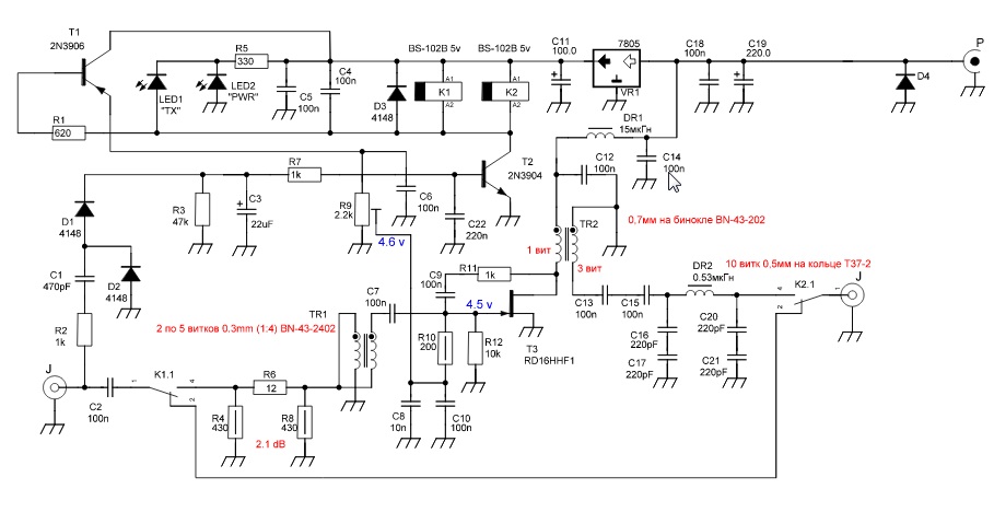
Nice PA
It looks like the schematic can be obtained from this page:
http://transverters-store.com/10w_pa.htm
By UT5JCW Serge
The link is part way down.
It looks like when RF is sensed T2 conducts closing the relays and turning on LED1.
If LED1 is on that tells me T2 Is conducting but either or both of the relays may not be closing.
Can you hear them clicking?
You may want to make sure you have 5V.
If that voltage is low the relays won't close.
Just some thoughts.....
73 Mark K3MSB
Where are all the CW ops?
I'm also very fond of the world below 530Khz.
Back when I was first licensed ~1990 there was still lots of maritime traffic on 500~512Khz, and between maritime and aviation beacons the spectrum between 190Khz and 450Khz was chock full of interesting activity, including the European LWBC stations.
But it
seems that all but a rare few of the maritime beacons are gone, the Aviation
NDBs are also being phased out pretty quickly, and the LWBC stations from
Europe are getting pretty thin, too.
With the end of the DGPS system, and all the other occupants of the LF and
lower MF range slipping into the twilight of history, I wonder what new use(s)
all that spectrum will ultimately be put to.
I can't
imagine it will remain unused...
I keep thinking what an exciting thing it would be to get a
*real* amateur allocation in the LF spectrum, say 160~190Khz (or something
thereabouts) on a Primary basis.
After
10+ years of limited experimentation under Part 5 licenses, hams have pretty
well proven that we can be good neighbors to the GRID/PLC and other industrial
users of the adjacent spectrum.
I remember touring the ARRL headquarters back in the mid 1990s (I
managed to sneak the extra day in at the end of a business trip to Hartford),
and they had "Old Bessie" on display out in the lobby - this was
allegedly Hiram's own personal rotary spark-gap transmitter... and what a beast
it was! I don't remember the exact spec's, but it was probably on the order of
2.5KW DC Input, just on my recollection of the two massive power transformers
under "the RF deck" - there was at least a hundred pounds of Iron down
there, and the wheel was about 20 inches in diameter, with like 12 or 16
spark-points around it's perimeter.
The
'Condensers' were the size of large coffee cans, and the ceramic
"pillar" insulators were each as big as a large cup of coffee.
The nostalgic stripe in me says we should have a day of the year
set aside for firing up such historic gear - and Part 97 be set aside for a
short span of hours - to the end of getting a few such stations "pounding
brass" the old fashioned way, down on LF, for the sake of history, so that
we could all get at least a sense of what radio was like when it was brand new,
all full of excitement and mystery.
But I dare say that the days of Ol' Bessie and the Wouf-Hong are long gone, and
never to return.
More's the pity; for the loss of those simple yet challenging
implements of our technical inspiration, coupled with an iron-clad sense of
moral propriety, were the benchmarks, and the hallmarks, of every great thing
which America achieved, throughout a century of unparalleled excellence in
essentially every aspect of life - which spanned roughly 1870 to 1970... and
now is plainly good and well through.
Or,
perhaps more likely, I was just born a century too late for my own happiness,
if not for my own good...
Anyway, back to NDBs and the LF spectrum - I've been meaning to
redo my arrangement of directional receive antennas for MF/LF - I'm thinking
something along the lines of a few Waller Flag antennas this time around.
They're supposedly as good as Beverages [pattern wise] from waht I've read, but with a much smaller footprint.
I had several complements of Beverages at one point - a pair of pairs pointed ~NE towards Europe (one pair for Eastern Europe and Moscow, the other for Western Europe and Britain), and another pair oriented due East/West - which were reversible so I could hear southern Asia and Africa, by whichever path was most profitable at the time.
But the deer here in the 'Carolinas don't know the difference between tree bark and PVC-clad copper, and so the upkeep on the beverages was an ongoing challenge, which I finally let go in favor of other activities.
But
I've recently pulled mt Drake R8 and Palstar R30A down from their shelf in the
closet, and been pondering what sort of wire I ought to excite them with... so
I'd be interested to hear your thoughts on the current state of the art in
MF/LF receive antennas.
73, Chuck
War on Hambands UA/UR ?
Listen 7050-7055 kHz, LSB
Hello
friends,
We
have a newcomer in the Cootie Zoo: John's - M0HTE Blackhawk:
http://www.sideswipernet.org/keys/m0hte-keys.php
Well
done John, lovely Cootie music from this instrument. Keep up the good work
mate.
Have a nice week gents, BCNU.
73, Yann, F5LAW.
73, your Editor Jan Pieter Oelp PA3CLQ
-30-
My simple website about Gigantic DF-Antennas
Part 1 "DF-Antenna Wullenweber Array"
Part 2 "DF-Antenna USSR Variants"
Part 3 "DF-Antenna USA Variant"
Next Part 4 "USSR OTHRA DUGA 1,2 & 3" at: