
PA3CLQ's Leuke Linken Nr. 451
I need clear explanations of Repeater Operation
Can anyone point me to clear explanations of how repeaters operate.
Were the terms Form A for Normally Open, Form B for Normally Closed, or Form C for one contact NO & one contact NC on the same armature common used among telegraphers or are they only industrial control terms which is were I learned them.
Thank you for any guidance anyone is up to supplying.
Tom Horne SlowSpeedWireGroup
REM :
No…The Form A, Form B, Form C terms were not used in telegraph repeater design or in repeater work.
They are modern electromechanical relay terms.
Basically, the design philosophy of a single line automatic telegraph repeater is to faithfully reproduce telegraph signals from one wire or line to another wire or line without human intervention.
The automatic repeater “set” usually consisted of four distinct parts: a receiving relay and a transmitter on the “west” side, and an identical receiving relay and transmitter on the “east side”.
The repeater design necessarily included a means of “locking” one receiving relay (say the “east” side receiving relay )while it’s companion transmitter responded to signals being received from the “west side” receiving relay and keyed the “east” line , and vice versa.
This was necessary to allow the sending operator on one line to “reclose” the circuit while sending towards the other line.
The WesternElectric “Athearn” repeater was a later more elegant design that used only two specially designed relays included in one unit with holding or locking coils that acted on the main relay armatures to lock one relay while the opposite relay was receiving and directly keying the opposite circuit.
AT&T used thousands of these fine repeaters, designated the 2A or 3A in it’s Morse telegraph network.
Read Franklin Pope’s “Modern Electric Telegraph” for a description of many of the repeater designs extant in the days of Morse Telegraphy.
Ed Trump ASST WC MTC & SlowSpeedWireGroup
See:
https://en.wikipedia.org/wiki/Franklin_Leonard_Pope
http://www.telegraph-history.org/pope/
https://archive.org/details/modernpracticeof00poperich
http://www.telegraphlore.com/pope/pope.htm
https://www.princeton.edu/ssp/joseph-henry-project/cyrus-brackett/motor.pdf
Editor
REM :
The following is from AT&T Co.'s Specifications 4068, February, 1921.
SINGLE MORSE REPEATER
Type of set.
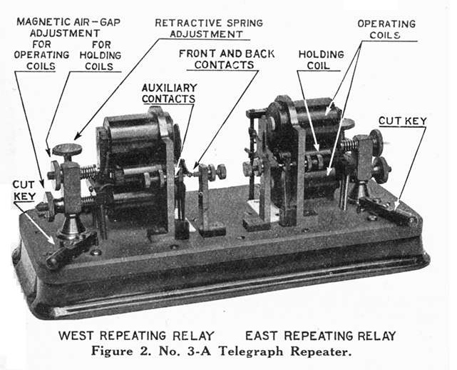
The No. 3-A telegraph repeater set as shown in Figures 2 and 3 is the standard of this company for repeating between two telegraph lines operated by the Single Morse system.
One of these lines may be merely the local circuit of a duplex repeater as explained later.
Description.
The No. 3-A telegraph repeater set is a direct point repeater in which the signals are repeated directly by the armature contact points of the main line relays, without the use of auxiliary transmitters or repeating sounders.
This set consists of two relays mounted on a single base.
One relay is arranged to have its line windings in series with the west line and its main contacts arranged to open and close the east line, while the other relay is arranged to have its line windings in series with the east line and its main contacts arranged to open and close the west line.
Each relay has a double-spool line magnet of 120 ohms resistance and a double-spool locking magnet of 10.5 ohms resistance.
The armature of each relay actuates two sets of contact points, one set being in the main line circuit and the second set or auxiliary contacts in the local circuit. The auxiliary contacts of one repeating relay serve to shunt the holding magnet of the other repeating relay and vice versa.
The line magnet, holding magnet and retractive spring of each repeating relay act in the same direction on the armature so that the armature is always bearing on the same side of the trunnions.
This arrangement prevents lost motion when the bearings become worn.
Switches are provided on the repeater set base for opening the local battery circuit when the set is not in use and for the purpose of separating the east and west lines.
The retardation coil, resistances and condensers which form a part of the set are mounted on the under side of the base.
The various adjustments of the set, which are referred to later, are indicated in Figure 2.
Explanation of Operation.
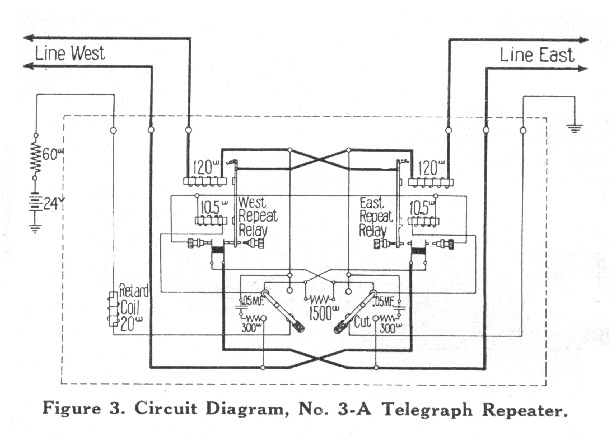
In Figure .3, the main line contacts of th& east repeating relay are shown to be open, as the key at the distant end of the east line is assumed to be open.
This relay is ready to repeat signals from the east line into the west line, which is assumed to be closed at its distant end.
The main line contacts of the west relay are held closed by the holding magnet of this relay, the shunt on this magnet having been opened when the east repeating relay opened its auxiliary contacts.
When the east line is closed, the armature of the east relay is actuated, closing the main line contacts and the auxiliary contacts of the east relay.
The main line contacts cause current to flow through the line magnet of the west relay and the auxiliary contacts shunt out the holding magnets of the west relay. The contacts of the west relay are therefore kept closed when the contacts of the east relay are either open or closed, provided the distant key of the west line remains closed.
This sequence of operations al)plies as well to the west relay when signals are being repeated from the west line into the east line.
If an operator in the west line opens a key to “break” while signals are being transmitted from east to west, the armature of the west relay will be released the instant the key in the east line is closed, since no current can flow through the line winding of the west relay while the west key is open, and current will be shunted out of the west holding magnet by the closure of the auxiliary contacts of the, east relay.
Consequently, the “break” will be transmitted to the east operator. The 20-ohm retardation coil in the locking circuit, through its inductive effect when the shunt on the holding magnet is removed, hastens the operation of this magnet.
The line contact points are shunted’ by a condenser and resistance in series to reduce the sparking.
The 1500-ohm non-inductive resistance reduces sparking at the auxiliary contact points.
The retardation coil, condensers and resistances are located in the base of the repeater set.
Uses.
The No. 3-A telegraph repeater set is used to connect two telegraph circuits together.
These telegraph circuits may be Single Morse circuits, half duplex circuits, or a Single Morse circuit and a half duplex circuit.
Return to the Athearn Morse Telegraph Repeater at:
http://www.telegraphlore.com/instruments/athearnrptr/athearnrptr.htm
Ed Trump FB
REM :
Hi Tom,
Ed is 100% correct (as usual :-).
I worked in the railroad signaling field which is just a specialized form of industrial control and the control systems were heavily relay based well into the 1980's (Microprocessor based "vital" systems have taken over much of the actual control logic but there still tend to be relays out there at the pointy ends.).
Anyway, we too referred to the various contact forms, A, B and C but in all my reading of telegraph technology publications I have never come across such designations.
For a little more on at least modern repeater systems such as the Athearn see the following links to the "Telegraph Lore" web site:
http://www.telegraphlore.com/instruments/halfduplex/halfduplex.htm
http://www.telegraphlore.com/instruments/athearnrptr/athearnrptr.htm
This web site has lots of useful information on it, here's the main link:
Another good site to check out is the "Telegraph-History" site:
http://www.telegraph-history.org/
73,
Chris Hausler SlowSpeedWireGroup
Here's
the new version of VIZ:
http://vizkey.com/order.html#90degreevizbug
I have
the vertical and it's a good bug. Basic, simple, works. Can't get better than
that.
Cheers & 73, Chuck VE7PJR
STRAIGHT
KEY NIGHT IS COMING!
24 hours of fun! Send "SKN" instead of RST!
http://www.arrl.org/straight-key-night
Too late? No, almost a year too early for that! (3clq)
When Everything Else Fails. Amateur Radio often times is our last line of defense...When you need amateur radio, you really need them.
"The Hon. W. Craig Fugate
Administrator,
US Department of Homeland Security, FEMA
Posted by Bry Carling AF4K (30-12-16)

Flameproof parts or parts key needed
eBay has the terminal cover:
Binding Post Cover & Screw Kit for Flameproof 26003A Telegraph Morse Code Key | eBay at:
73, Robolt
I added Gas discharge tubes voltage regulation to my ARC5 Xmtr.......
osc and screen voltage supply and got it CHIRP FREE !
John Davidson k8jd
REM :
CHIRP FREE???
I don't think that is allowed for NRR!!
You'll have to work on that!!
...Dave
REM :
Hi John
You can get an ARC-5 to be chirp free on 40 meters without doing that.
Alternately,
you can do that and still have a chirp.
One of the primary reasons for chirp is 75 year old solder joints that develop
cracks.
My
BC-459 was pretty bad until I touched up all the solder joints, and the chirp
improved considerably (or decreased depending on your perspective).
I'm adding a T-19 and T-22 to work with my BC-348Q and the power supply will
probably use regulators as you mention.
My plan (and we all know how plans go.....) is to use my SCR-274N primarily for AM, and use the T-19, T-22, and BC-348 primarily for CW.
Ah, plans.....In any event, I haven't had the T-19 and T-22 on the air in a few years.
The T-19 sounds fine on 80, but the T-22 sounds a bit iffy on 40. We'll see how it goes.
73 Mark
K3MSB
REM :
Dave, this was back in the 60's where chirp was considered lowbrow by the guys with the Johnson and Collins gear.
John Davidson
"Dot and Dash," or "Dit and Duh" ???
There is a line of distinction between the vocabularies of people who work Morse, and those who work with Continental.
Morse telegraphers say "Dot and Dash." Our radio friends say "Dit and Duh."
After menioning this to several people in the recent past, I was urged to write up what I know about the subject, so here it is, taken from notes I made in 1978.
For a number of years I was on the Philadelphia Leased Telegraph Wire, the "Ace Holman Wire" (although Ace would have eschewed such a term ! )
There were seven subscribers to the Wire during my time there (which ended in 1981, when I was transferred by my company to another city.)
The two oldest operators on the Philadelphia wire were George Van Dyke, Ph.D., a retired U.S. Navy Commander who, at the time, was doing some part time teaching for General Electric, and Ralph Williams E.E. who worked for RCA (Radio Corporation of American) Both had been involved with radio since 1920.
George VanDyke had been a Navy radio operator beginning in 1920, and was obliged to learn Morse due to the fact that, when his ship came into port, it was connected to Western Union wires and the Navy operators worked those circuits with Morse, not Continental.
George lived in the Torresdale section of northeast Philadelphia and used the office call "VN."
Ralph Williams had been an amateur radio operator since 1920, using Continental, and I do not recall where Ralph learned Morse.
Ralph lived in King-of-Prussia, Pa, and used the office call "WA" since his post office address was Wayne, Pa.
Since George and Ralph had both been involved with radio since its early days, I asked them about why Morse people said "Dot and Dash," but radio people said "Dit and Duh."
They both laughed and said that in the early days of radio, radio operators had also said "Dot and Dash," but that during the 1940s, when the Army and Navy wanted to speed up the teaching of Continental code to their radiomen, someone thought "Dit and Duh" would make things simpler for the learners.
And thereafter, "Dit and Duh" somehow "stuck" in radio vocabulary.
I also consulted with Ace Holman about this, and told him what George and Ralph had related to me. Ace's response was, "That sounds right to me." (But Ace didn't become involved with radio Continental radio code until the late 1930s and, if I recall correctly, he learned Morse in 1942 when he went to work for AT&T, so he was not a radio operator in the "early days.")
One final item of confirmation on this subject.
My own telegraph teacher was Harry Clark, who learned Morse at the Dodge Institute of Telegraphy in Valparaiso in 1920.
Harry was a boomer railroad and Western Union telegrapher (20 different railroads, WU, Postal, a brokerage wire, even a shoe company order wire, plus telegraphing on commercial circuits in Mexico City ! ), But Harry had picked up a knowledge of Continental somewhere along the line, just as a matter of curosity. Harry said that if he found another operator on the telegraph wire who knew Continental, they would sometimes, in the quiet hours of the third trick, chat in Continental just for diversion.
Shortly before his untimely death, I wrote Harry about the story I had received from George and Ralph, about "Dit and Duh" being military jargon.
Harry wrote back saying that he had never heard the terms "Dit and Duh" before the 1940s, either.
Sent to You from my Telegraph Key Successor to the MAGNETIC TELEGRAPH LINE of 1844
-- 73 SW & abram burnett
Posted by: pravoslavna
REM :
Actually, the radio jargon is “di” and “dah”
The Continental, or International “sound” for the letter “B” is “ dahdididit”.
And so on. Ed. FB
REM :
I remember Ralph Williams well.
Ralph was an authority on Atwater Kent radios.
He had a house full of them, and if I recall correctly, he had a beautifully restored example of every model made, including the variations of the "breadboard" models.
The Toledo Chapter also had a leased wire similar to that in Philly.
It was called the "United Wire Service," and if my memory serves, it was primarily the brain child of Al Leonard, who served as wire chief and the liaison to AT&T. Al had a nice piece of artwork above his operating desk which featured a large "73," within the laurel wreath.
I'm a bit suspect of the "di" "dah" emerging in the 1940s.
I have seen a number of documents dating from the '20s in which the Continental Code is described as "dit" and "dar" and later "di" and "dah," as in "di-dah-dit."
A lot of radio operators in the teens and 20s learned using a buzzer for code practice. The "dar-di-dar-dit" does a good job of approximating the sound of a buzzer.
The "dah-di-dah-dit" does a good job of approximating a more pure tone, such as from a vacuum tube oscillator.
I have filed away the records of the Indian Radio Club of Pontiac, Michigan, which I obtained from the son of the Club Treasurer.
The club disbanded in 1929 when the Depression hit.
Included is a box of "Century Buzzers," new in their boxes ready for new hams wishing to learn code, as well as various minutes, local rules and regulations, and the first radio receiver installed in the City of Pontiac to receive time signals from NAA.
Along with the latter is the contract for installing the antenna and similar documents.
Some of the stuff is quite interesting to read.
73, JW James Wades International President, Morse Telegraph Club, Inc.
REM :
Morse & Vail originally intended that telegraphy would be read visually from the output of Paper Tape Registers.
In that context dot and dash would make perfect sense.
With the rapid transition to receiving by ear the instructors developed a variety of techniques for teaching telegraphy.
Perhaps Di Dah were a product of their experimentation.
Tom Horne
REM :
Hi Tom,
In fact my reprint of the 1866 issue of Prescott describes this on page 89. In describing how to time ones sending with a straight key (the only kind available at that time :-) it says as follows:
"Each beat of the first kind is measured by the syllable di, which is pronounced while making the beat; with regard to the beats of the second kind, they are measured by pronouncing the syllables do-o.
The beats that are made while pronouncing the di would produce dots, and those which are made while pronouncing do-o would give dashes..."
Of course this doesn't imply using these sounds to represent dots and dashes, just how to time their sending.
But one can see where this might be going :-)
73, Chris Hausler
The
SKCC 2017 Calendar PDF is now available for download.
It shows CW events of interest to mechanical key operators, historical dates,
US holidays, moon phases, meteor showers and K3Y QSL card designs.
Approx
5MB. Download from the K3Y page here:
http://www.skccgroup.com/k3y/k3y-docs/SKCC_2017_Calendar.pdf
73, Drew AF2Z
73, from the town at the rivers "De Bergsche Maas" and "De Dongen" Geertruidenberg (800+ years city rights) at: 51.702211N 4.853854E
Your Editor Jan Pieter Oelp PA3CLQ
-30-
My simple website about Gigantic DF-Antennas
Part 1 "DF-Antenna Wullenweber Array"
Part 2 "DF-Antenna USSR Variants"
Part 3 "DF-Antenna USA Variant"
Next Part 4 "USSR OTHRA DUGA 1,2 & 3" at: