
PA3CLQ's Leuke Linken Nr. 452
Camel-back straight key question
Does the Camel-back straight key design have an advantage over the conventional straight arm found on many other keys?
Thanks, John WN4OFT
REM :
If
"it's prettier" is an advantage, that'd be about the only one. (grin)
I understand it was an early attempt to get around "Telegrapher's
Cramp."
Unfortunately it doesn't do that.
Nor
does the famed "Chubbock" key with its off-centre trunnion.
As the only remedy for a repetitive stress injury is to stop the repetitive
motion, a sideswiper or a bug or other keying device such as a keyer run by
"electrickery" that utilizes the side-to-side motion is the surest
cure.
73, Chuck Hays VE7PJR
REM :
Hi John,
The advantage of the camel back key is that it is lower to the desk than a straight lever.
Basically there are 2 types of keying:
American style - resting your arm on the desk
European style - not resting your arm on the desk
The camel back key was designed to place the key's lever lower by bending it over the pivot assembly to better accommodate American style keying.
With
your arm resting on the desk, you don't have to bend your wrist or elbow as
much to reach the key.
I don't rest my arm on the desk when using a straight key so it doesn't make
much difference to me.
However
I rarely use a straight key anymore because I'm hooked on Cootie Keys (aka Side
Swipers).
73, Art, W2NRA
REM :
Hi John.
I'd recommend this site for info.
Morse Key History | Telegraph Keys | Electronics Notes at:
https://www.electronics-notes.com/articles/history/morse-code-telegraph/morse-key-development.php
73 Chris NW6V
REM :
John, haven't seen any response so I'll throw out my comments.
Key for key overall, I personally don't think there is much if any particular advantage or disadvantage in either, mechanically it depends on the build characteristics for either style - length of shaft, type of tension, bearings, etc.
I measure a key at the knob or paddle: to me the differences are in feel and preference, how you adjust and operate the key.
I prefer a very light tension for gap separation, and a very narrow gap - the thickness of one sheet of standard bond paper, I adjust my J38's the same as my VisKey Camelback.
Adjusted as such, it takes a very light finger touch rather than the 'pounding/slapping' I used to do.
I find I can use either my J38 (original base) or my camelback (heavier brass base) without any wandering at all.
I do prefer the magnetic tension over the leaf spring, and the leaf-spring over the coil spring - I think they have a smoother, more consistent feel.
Must say that I think there is very little felt difference in the magnet and the leaf spring.
I already had a leaf spring key when I tried a magnetic tension key, I liked it a little more but the difference wasn't enough to influence me to change.
My first good paddle was a K8RA P2 dual lever paddle with the magnetic tension option, very sweet key! It and my VisKey Camelback totally fill my daily requirements.
Just food for thought - hope you get more responses with additional opinions and 'measurements' so to speak.
Cray / K5MUG
Show time in Window
You
can find the downloadlink on my QRZ.COM page and you have a Clock which font
can be sized as big you want and more like ontime counter, offline counter
...That´s it.
https://app.box.com/s/ga5fy4nn2iuy7f6ud09ugp1geyt6k5ui
Hi,
I made some more changes in my N1MM Toolbox SW - download on
https://app.box.com/s/ga5fy4nn2iuy7f6ud09ugp1geyt6k5ui
1.
Added a CDT Timer - which show the remaining time until a contest start (can be
set via shift + click on "Clock" button
2. Some changes in behaviour of the windows
Updated the readme document as PDF.
Greetings Have fun Peter DF1LX
Project Manhigh 1 test flight saved by Morse code
I’m reading the book “Breaking the Chains of Gravity: The Story of Spaceflight before NASA” and just finished the chapter that highlighted the Project Manhigh stratospheric balloon flights.
About 20 minutes after the launch of Manhigh 1 on June 2nd 1957, piloted by Captain Joseph Kittinger, the VHF radio used for air to ground communication malfunctioned.
The gondola was also equipped an HF telemetry transmitter and HF voice receiver, which he could use to receive transmissions from the flight center.
Captain Kittinger used the telemetry transmitter in the cw mode to transmit to the Winzen Research plant (where the gondola and balloon were built).
The transmissions were decoded and relayed by phone to the flight center.
Even with the delay caused by relaying messages, the mission was still mostly a success even though oxygen supply problems forced an end to the mission 2 hours after reaching a peak altitude of about 95,200 feet.
Don’t know if he was a ham at that time, but I did read an excerpt from his autobiography where he talked about using a portable 2 meter radio during a cross-country gas balloon flight in 1981.
Could not find many detailed pictures of the inside of the gondola but I found a drawing that showed the position of a code key mounted close to where the pilots right hand would be.
73, John WN4OFT
REM :
https://www.amazon.com/Breaking-Chains-Gravity-Spaceflight-before/dp/1511365439
http://www.goodreads.com/book/show/22312378-breaking-the-chains-of-gravity
http://www.bloomsbury.com/us/breaking-the-chains-of-gravity-9781472911193/
http://www.space.com/32192-breaking-chains-of-gravity-book-excerpt.html
a.s.o.
Editor
Hello
friends,
Have
a look at Brian's - G4CJY homebrew sideswiper:
http://www.sideswipernet.org/keys/g4cjy-keys.php#homebrew1
I hope to have him back soon on the EU SSN with us and will send him an invitation to join this reflector.
Brian
wrote:
"Yann thank you for your invitation to join the net, my 80 and 40m
verticals need retuning at present and when sorted, I will come up.
Please qsp HNY to all on the net and hope to join soon."
Propagation.
Hi Jean and the SSN-Group.
This won't be of any surprise to you, but for me it was very instructive.
I ran VOACAP for the path between AA7FV and London.
I set the SSN to zero (which it's been recently), and ran the prediction once for a minimum elevation angle of 5 degrees, and once for an elevation of 0.1 degrees. (The minimum elevation from AA7FV towards London is actually 6 degrees, set by a ridge of mountains to my north.)
The two predictions are shown below.
The interesting thing to me is that, following the horizontal line for 20m, the beginning of the opening on this path is close to 14:00 UTC for both predictions, and in both peaks at about 16:00 UTC.
However, with the lower elevation angle the opening lasts about one hour longer (to just after 18:00 UTC) than with the higher propagation angle limit, where it ends soon after 17:00 UTC.


This won't be any surprise to anybody like yourself who understands propagation, but I found it very interesting to see.
Cheers, Darrel, aa7fv.
Hello friends,
As I want to know where my signals go, I modeled my dipole 2x15m
These images give us a rough idea of my signals to ssn stations.
To take caution, because it is only a simulation.
15 meters 17meters 20meters
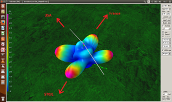
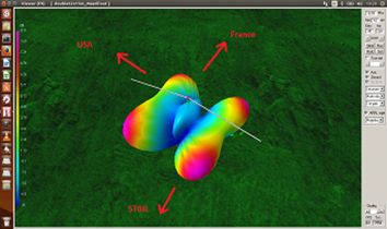
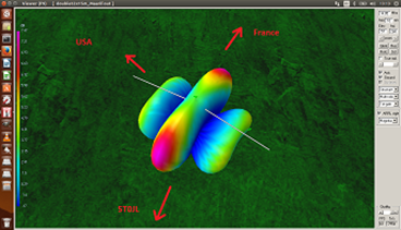
73, Med CN8YR
About 20 meters
I used EZNEC-Pro to model the same thing, giving (no surprise) the
same result.
Here's a wire-frame plot of the same, 3-D pattern from
EZNEC-Pro. Not nearly so pretty as yours, but the calculated pattern is I think
identical:
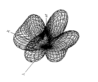
I then just plotted the azimuth pattern, for an elevation angle of
10 degrees.
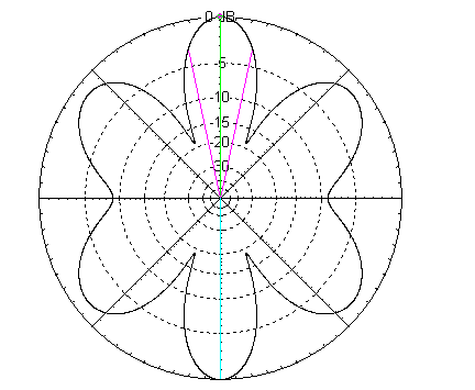
I've rotated the antenna in this plot compared to your plot, so
that the wire now runs left-to-right.
The highest gain lobe, which is vertical in this plot and labelled "to
France" in your plot, and is at right angles to the wire, has a beamwidth
of only 24 degrees - i.e. +/- 12 degrees.
Note that when you say "in the direction of the
USA", you probably need to say which part of the USA. For example, from CN
the state of Florida has an azimuth of about 290 degrees, while the state of
Washington from CN has an azimuth of more than 320 degrees. (From CN to AA7FV
the azimuth is about 304 degrees.) That's more than a 30-degree range of
azimuth, which is significantly greater than the potential beamwidth of your
antenna.
The pattern of your antenna in the direction that you've marked "to the
USA" has a double lobe, especially at low elevation angles. Depending on
elevation angle, in the direction between the 2 lobes (horizontally to the left
in my plot above), the pattern is some 10 dB weaker than the strongest lobe of
your antenna.
This is all on 20m. Of course, the pattern gets a little
more complicated at higher frequencies. And, as you said yourself, this is just
a model. It will be modified by the presence of other antennas, trees,
buildings etc.
Just for fun! Cheers, Darrel, aa7fv.
Hello friends,
Here are some pattern for 15/17/20m for the best take off angle.
All these patterns show that Jean 5T0JL is in the nulls, but only for the best angle.
There are other angles more higher, good for short distance as (CN--->5T), for which nulls disappear.
North is 90° in the pictures, but beaming is 0° at North and counting in a clockwise direction.
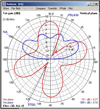
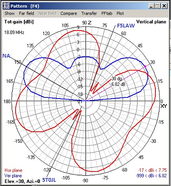

73, Med CN8YR
BTW, I've added a link to VKCW.net in
the resource page:
http://www.sideswipernet.org/resources.php#links_general
Congratulations to David - VK2JDR and the team for this great resource.
Have
a nice day gents, BCNU SN.
http://www.sideswipernet.org/
73, Yann, F5LAW.
73, from the town at the rivers "De Bergsche Maas" and "De Dongen" Geertruidenberg (800+ years city rights) at: 51.702211N 4.853854E
Your Editor Jan Pieter Oelp PA3CLQ
-30-
My simple website about Gigantic DF-Antennas
Part 1 "DF-Antenna Wullenweber Array"
Part 2 "DF-Antenna USSR Variants"
Part 3 "DF-Antenna USA Variant"
Next Part 4 "USSR OTHRA DUGA 1,2 & 3" at: